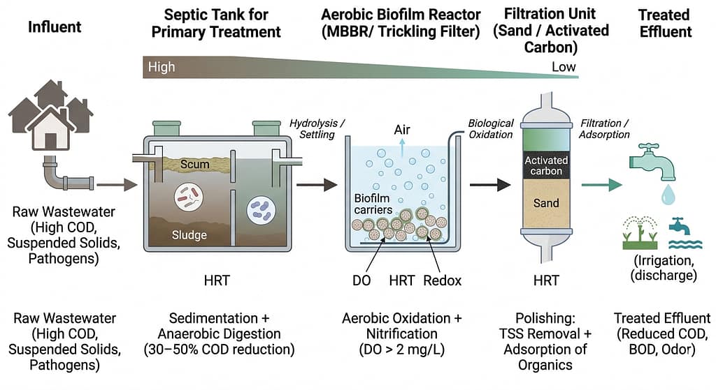
Decentralized wastewater treatment systems are increasingly vital in regions where centralized municipal sewer infrastructure is economically unfeasible, geographically challenging, or operationally unreliable. Rather than relying on a single treatment mechanism, decentralized plants combine primary anaerobic digestion with high-rate aerobic biofilm oxidation and tertiary polishing filtration to achieve stable contaminant removal under fluctuating field conditions.
System Overview: Sequential Unit Operations
The treatment train is structured into three continuous biochemical and physical separation phases:
- Anaerobic Stage (Septic / Hydrolytic Tank): Bulk suspended solids sedimentation and partial anaerobic digestion.
- Aerobic Stage (Biofilm Reactor / MBBR): Biochemical oxidation of dissolved organics and autotrophic nitrification.
- Polishing Stage (Multi-Media Filtration & Adsorption): Removal of residual TSS, turbidity, and recalcitrant organics.
1. Primary Treatment: Septic Tank (Anaerobic Phase)
The septic unit functions simultaneously as a physical gravity clarifier and a low-rate anaerobic digester. Raw influent undergoes:
- Sedimentation: Settleable solids drop to the bottom sludge layer under laminar settling regimes.
- Flotation: Grease, oils, and fats float upward to form an airtight scum blanket.
- Anaerobic Hydrolysis: Acidogenic bacteria break down complex carbohydrates, proteins, and lipids into volatile fatty acids (VFAs).
| Operational Parameter | Typical Design Range | Process Impact |
|---|---|---|
| Hydraulic Retention Time (HRT) | 12 – 24 hours | Ensures quiescent settling and enzymatic breakdown |
| COD Removal Efficiency | 30% – 50% | Reduces organic load before downstream aeration |
| TSS Removal Efficiency | 50% – 70% | Prevents downstream biofilm carrier clogging |
2. Secondary Treatment: Aerobic Biofilm Reactor (MBBR)
Following anaerobic pre-settling, clarified wastewater enters an attached-growth aerobic reactor, such as a Moving Bed Biofilm Reactor (MBBR) or trickling biofilter:
- Biofilm Attachment: Microorganisms colonize high-surface-area virgin HDPE carriers (typically >800 m2/m3 specific protected area) maintained in suspension by continuous aeration.
- Aerobic Mineralization: Heterotrophic bacteria oxidize dissolved organic carbon into CO2 and biomass under positive dissolved oxygen (DO > 2.0 mg/L).
- Biological Nitrification: Autotrophic nitrifiers convert toxic ammonium (NH4+) into nitrite (NO2–) and nitrate (NO3–) via Nitrosomonas and Nitrobacter pathways.
This aerobic phase delivers an additional 40%–70% COD reduction and up to 90%–95% cumulative BOD removal across the plant.
3. Tertiary Treatment: Filtration and Activated Carbon Adsorption
The final polishing module comprises dual-media sand filtration followed by granular activated carbon (GAC):
- Sand/Anthracite Filtration: Captures sloughed biofilm fragments and fine suspended solids down to <10 μm.
- GAC Adsorption: Activated carbon offers expansive internal microporosity (BET surface area >900 m2/g), capturing micropollutants, surfactants, lingering odors, and phenolic color compounds.
Integrated Performance and Design Standards
| Metric | Raw Influent | Final Polished Effluent | Overall Removal |
|---|---|---|---|
| COD (Chemical Oxygen Demand) | 1,800 – 2,500 mg/L | 150 – 350 mg/L | 75% – 90% |
| BOD (Biochemical Oxygen Demand) | 600 – 1,100 mg/L | <30 mg/L | >95% |
| TSS (Total Suspended Solids) | 400 – 800 mg/L | <20 mg/L | >95% |
💧 Bioprocess & Wastewater Treatment Engineering
BioFlo designs custom biological wastewater plants, MBBR reactors, and industrial effluent treatment solutions with complete hydrodynamic and kinetics modeling.
Consult with a Water Treatment Specialist →\ Get the latest news /