

⚡ Executive Summary for Bioprocess Engineers & MSAT Leads
- The Critical Post-Mix Kinetic Window: Impingement jet and microfluidic mixers eject an unstable colloidal intermediate containing 20–33% (v/v) ethanol at pH 3.8–4.2. Unquenched intermediates undergo rapid Ostwald ripening and mRNA phosphodiester backbone hydrolysis if buffer exchange does not initiate within a strict 2 to 4-hour processing window.
- The Hydrodynamic Shear Boundary: mRNA-LNPs are soft, deformable mesophase vesicles (60–100 nm). Exposure to wall shear rates γw > 4,000–6,000 s-1 (wall shear stress τw > 4–6 Pa) rips the protective PEG-lipid shell away from the core, causing immediate payload leakage, particle fusion, and an irreversible spike in polydispersity (PDI > 0.20).
- Hollow Fiber vs. Flat Sheet Cassettes: Hollow fibers provide parabolic laminar flow with uniform wall shear stress, making them the industry gold standard for fragile mRNA/gRNA-LNPs. Flat-sheet cassette screens create micro-vortices that enhance permeate flux (40–60 LMH vs 20–35 LMH for HF) but generate localized stagnation-point shear peaks that degrade yield.
- Diafiltration Volume Dynamics: Reducing residual ethanol from 250,000 ppm (25%) down to the strict ICH Q3C safety ceiling (<5,000 ppm) and clinical target (<50 ppm) requires a mathematically verified 8.5 to 9.0 diavolumes (DV) operating strictly in permeate-flux controlled mode.
- The 0.22 μm Sterile Filtration Clogging Crisis: Why 80 nm nanoparticles regularly blind 220 nm sterilizing filters—and how dual-layer asymmetric polyethersulfone (0.8/0.2 μm) membranes and strict transmembrane pressure limits (ΔP ≤ 0.5 bar) prevent pore bridging and premature fouling.
In the rapidly maturing landscape of genetic medicines—spanning prophylactic mRNA vaccines, systemic siRNA therapies, and in vivo CRISPR/Cas9 ribonucleoprotein delivery—the industry spotlight frequently fixates on the microfluidic formulation mixer. Yet ask any downstream process development scientist or cGMP manufacturing lead, and they will tell you the uncomfortable truth: mixing creates the nanoparticle, but tangential flow filtration (TFF) and sterile filtration make the medicine.
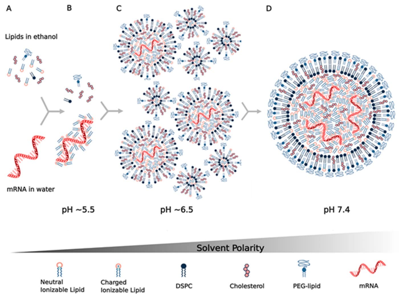
A lipid nanoparticle directly exiting an impingement-jet or staggered herringbone mixer is fundamentally unfit for clinical administration. It is dissolved in 20% to 33% (v/v) organic solvent (ethanol), acidified to pH 3.8–4.2 to keep the ionizable lipid positively charged, and contaminated with unencapsulated nucleic acids, free lipid monomers, and empty micelles. If left in this post-mix state, the nanoparticles rapidly undergo Ostwald ripening, size escalation, and acid-catalyzed hydrolysis of the sensitive mRNA cargo.
Purifying this mixture requires solving a high-stakes biophysical balancing act: you must rapidly clear tens of thousands of parts per million of toxic solvent, swap millions of liters of buffer, and concentrate the batch—all while handling an extraordinarily shear-sensitive, soft colloidal nanoparticle that cannot tolerate the mechanical stresses standardly applied to monoclonal antibodies or recombinant proteins.
This comprehensive guide breaks down the chemical engineering, membrane fluid dynamics, mathematical modeling, and operational failure modes of advanced LNP filtration.
1. The Post-Mixing Intermediate: What Enters the Filtration Suite?
To engineer an effective downstream filtration process, one must first dissect the physical and chemical state of the fluid stream exiting upstream formulation. A standard clinical mRNA-LNP platform consists of four distinct lipid excipients formulated at strict molar ratios:
- Ionizable Cationic Lipid (40–50 mol%): (e.g., SM-102, ALC-0315, DLin-MC3-DMA) with an apparent pKa of 6.2–6.8. At pH 4.0 during mixing, tertiary amines are protonated (>99% positive charge), electrostatically condensing polyanionic mRNA into a high-density, electron-dense non-bilayer core.
- Neutral Helper Phospholipid (10 mol%): Typically 1,2-distearoyl-sn-glycero-3-phosphocholine (DSPC) or DOPE, forming structural bilayer stabilization and facilitating hexagonal phase transitions during endosomal release.
- Cholesterol (38.5–40 mol%): Fills interstitial voids within the lipid assembly, tuning membrane rigidity, particle packing density, and circulation stability.
- PEGylated Lipid (1.5–2.0 mol%): (e.g., PEG-2000-DMG or ALC-0159). The steric hydrophilic PEG chains decorate the nanoparticle surface, thermodynamically limiting particle growth to a precise 60–100 nm window and preventing colloidal aggregation in aqueous storage.

The Three Mandates of Downstream LNP Filtration
When this formulation intermediate enters the downstream filtration suite, the unit operation must execute three simultaneous thermodynamic and chemical transformations:
- Physiological Neutralization & Core Solidification: Exchanging the acidic formulation buffer (citrate or acetate, pH 4.0) with physiological buffer (PBS or Tris, pH 7.2–7.5). As the pH crosses the lipid pKa, the ionizable amine heads deprotonate, shedding their charge. This causes the internal core to collapse into a stable, water-impermeable, hydrophobic lipid-RNA matrix, locking the mRNA payload in place and raising encapsulation efficiency (EE) to >90–95%.
- Residual Solvent Clearance: Ethanol in the post-mix intermediate ranges from 200,000 to 330,000 ppm (20–33% v/v). According to ICH Guideline Q3C (R8) on Impurities: Residual Solvents, ethanol is a Class 3 solvent with a permitted daily exposure of 50 mg/day, translating to a mandatory regulatory limit of <5,000 ppm (<0.5%). Most commercial mRNA drug substance specifications enforce an internal release threshold of <50 to <500 ppm to ensure long-term shelf stability.
- Volumetric Concentration & Cryoprotectant Addition: Because microfluidic and impingement mixing operate at dilute mRNA concentrations (typically 0.05–0.15 mg/mL) to avoid bulk precipitation, TFF must concentrate the retentate by a Volumetric Concentration Factor (VCF) of 5× to 15× to reach commercial drug product concentrations (0.50–2.00 mg/mL), followed by diafiltration into cryoprotectant buffers (8–10% sucrose or trehalose).
2. Tangential Flow Filtration (TFF) Mechanics & Membrane Shear Limits
Traditional normal-flow (dead-end) filtration cannot be used for post-mix LNP purification. Directing an LNP suspension perpendicularly into a filter cake causes immediate, irreversible fouling: the high local concentration of soft lipid vesicles forms a compressed, impermeable gel layer across the membrane face within seconds, starving flow and destroying the nanoparticles.
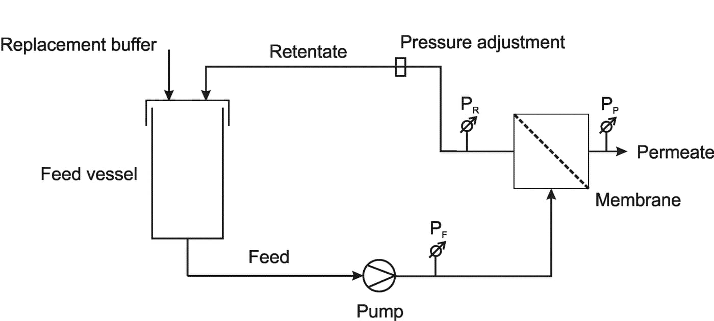
Instead, bioprocess engineers rely on Tangential Flow Filtration (TFF), where process fluid recirculates parallel to the semipermeable membrane face at high velocity. The sweeping crossflow creates hydraulic shear stress that continuously scours foulants, nanoparticles, and concentration boundary layers off the surface, returning them to the retentate vessel while driving solvent, salts, and unencapsulated impurities through the porous matrix into the permeate line.
Governing Equations: Transmembrane Pressure & Wall Shear Rate
Process engineers operate TFF skids by continuously balancing two primary hydraulic driving forces:
1. Transmembrane Pressure (TMP):
TMP = (Pfeed + Pretentate) / 2 − Ppermeate
TMP represents the average hydraulic driving force pushing solvent through the porous membrane wall. For LNP operations, TMP is tightly capped between 0.30 and 0.85 bar (4.5 to 12.0 psi). Exceeding 1.0 bar compresses the flexible LNP outer shell, driving irreversible membrane pore compaction.
2. Wall Shear Rate (γw) in Hollow Fibers:
γw = 4 × Qfiber / (π × r3) = 8 × v / di
Where v is crossflow linear velocity (m/s), di is inner lumen diameter (m), and Qfiber is volumetric flow rate per individual fiber lumen (m3/s). For standard 0.5 mm ID hollow fibers, operating crossflow velocities of 0.5–1.5 m/s correspond to wall shear rates of 2,000 to 4,500 s-1.
The Hydrodynamic Shear Cliff: Why LNPs Are Not Proteins
Monoclonal antibodies (mAbs) are compact globular proteins (molecular weight ~150 kDa, hydrodynamic radius ~5 nm) stabilized by extensive intramolecular covalent disulfide bonds. In antibody processing, TFF skids routinely operate at aggressive crossflow velocities with wall shear rates exceeding 10,000 to 16,000 s-1 without loss of monomer purity.
In stark contrast, lipid nanoparticles are non-covalent, self-assembled, fluid supramolecular architectures held together solely by hydrophobic interactions, van der Waals forces, and electrostatic screening. Under intense fluid shear stress (τw = η × γw):
- PEG-Lipid Stripping: The hydrophilic PEG-2000 chains exert steric drag against the crossflowing fluid. If local wall shear stress exceeds ~5 Pa, the lipid anchor (DMG or DSPE) desorbs from the outer monolayer into the aqueous bulk. Deprived of its steric shield, the bare hydrophobic lipid core undergoes uncontrolled particle-particle collision and fusion.
- Cargo Leakage: High local shear gradients deform spherical LNPs into prolate ellipsoids. If elongation exceeds the critical capillary number (Ca > Cacrit), transient pore defects tear through the lipid shell, leaking encapsulated mRNA into the retentate where it is exposed to residual nucleases.
- Ostwald Ripening Acceleration: Shear-induced energy dissipation accelerates the rate at which lipid monomers transfer from smaller vesicles to larger ones, causing rapid broadening of the particle size distribution (PDI jumping from 0.08 to >0.25).
⚠️ The Industrial LNP Shear Limit: In cGMP biomanufacturing, process engineers enforce an empirical maximum wall shear rate γw,max ≤ 4,000–5,000 s-1 across all pump heads, valves, flow channels, and membrane modules. Any skid design featuring high-shear centrifugal pumps, restrictive needle valves, or high-screen turbulence promoter cassettes risks catastrophic batch yield failure.
3. Hollow Fiber (HF) vs. Flat Sheet Cassettes: The Definitive Battle
The central decision point when configuring an LNP TFF unit operation is selecting the physical membrane geometry: Hollow Fiber (HF) Modules versus Flat-Sheet Cassettes.
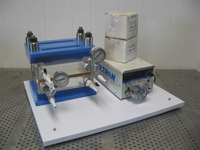
Both architectures have passionate defenders across biopharma. Here is the rigorous engineering comparison:
| Engineering Parameter | Hollow Fiber (HF) Systems | Flat-Sheet Cassettes (Screens) |
|---|---|---|
| Flow Hydrodynamics | Smooth, open cylindrical lumen. Pure parabolic Hagen-Poiseuille laminar flow profile. | Narrow rectangular channels packed with woven polypropylene or polyester turbulence promoter screens. |
| Shear Distribution | Uniform & Predictable: Shear is zero at lumen center and reaches well-defined maximum at wall (γw ≤ 4,000 s-1). Zero stagnation points. | Heterogeneous / Shear Peaks: Screen filaments induce Dean vortices with localized shear rates reaching >12,000 s-1 at filament stagnation points. |
| Average Permeate Flux (J) | Moderate: 18 – 35 LMH (L/m2/h). Requires larger membrane area for equal process time. | High: 35 – 65 LMH. Screen vortices disrupt the boundary layer, enhancing mass transfer rate. |
| Minimum Working Volume | Higher hold-up volume per m2 due to fiber header end-caps and manifold geometries. | Ultra-Compact: Extremely low hold-up volume, enabling higher volumetric concentration factors (VCF > 20×). |
| Membrane Chemistry | Predominantly Modified Polyethersulfone (mPES). Low protein/lipid adsorption; broad pH stability (1–14). | Regenerated Cellulose (Hydrosart) or PES. Regenerated cellulose exhibits exceptionally low hydrophobic lipid binding. |
| Single-Use / Gamma Sterility | Widely available in pre-sterilized, gamma-irradiated, glycerin-free single-use assemblies. | Available in single-use self-contained formats (e.g., Pellicon Capsule), but traditionally requires stainless holder assembly. |
| Industry Consensus | Primary Choice for Fragile mRNA-LNPs (high mRNA retention, minimal PDI shift, gentle processing). | Preferred when processing time must be minimized and hold-up volume is critical, provided open screens (V-screen or D-screen) are used. |
Membrane Cut-Off (MWCO) Selection: The 100 kDa vs 300 kDa vs 500 kDa Dilemma
Unlike proteins whose molecular weight dictates membrane cut-off (typically selecting MWCO at 1/3 to 1/5 of the target protein’s mass), LNPs are immense multimolecular complexes:
- An 80 nm LNP has an apparent molecular mass exceeding 10,000 to 50,000 kDa (>10–50 MDa).
- Free, unencapsulated therapeutic mRNA molecules (1,000–4,000 nucleotides) possess molecular weights between 300 kDa and 1,300 kDa.
- Free lipid monomers and small mixed ethanol-lipid micelles possess molecular weights of 0.7 to 50 kDa.
Consequently, selecting membrane MWCO is not about retaining the LNP—any ultrafiltration membrane will retain 100% of intact LNPs. The real challenge is preventing pore constriction by free lipid micelles while enabling the clearance of unencapsulated mRNA fragments:
- 100 kDa MWCO (Too Tight): While providing absolute retention, 100 kDa membranes suffer rapid flux decay during early diafiltration. High concentrations of free lipid monomers and micelles deposit into the sub-micron pore necks, forming a dense cake that reduces permeate flux by >70%. Furthermore, unencapsulated mRNA is completely retained, artificially inflating total nucleic acid assay values without contributing to active encapsulated product.
- 300 kDa MWCO (Industrial Sweet Spot for Short RNA): The standard workhorse for siRNA and shorter mRNA constructs (<1,500 nt). Offers stable permeate flux (25–35 LMH in hollow fibers) while completely rejecting LNP vesicles.
- 500 kDa / 750 kDa MWCO (Optimal for High-Yield Commercial Platforms): Modern commercial mRNA-LNP processes increasingly standardize on 500 kDa or 750 kDa mPES hollow fibers (or 0.05 μm microfiltration). The wide pore channels allow free, unencapsulated single-stranded mRNA and lipid micelles to permeate rapidly into the waste stream, achieving high analytical purity (>95% encapsulation efficiency) with sustained volumetric flux (>35–45 LMH) throughout 10 diavolumes.
4. Diafiltration Mechanics & Residual Ethanol Clearance Modeling
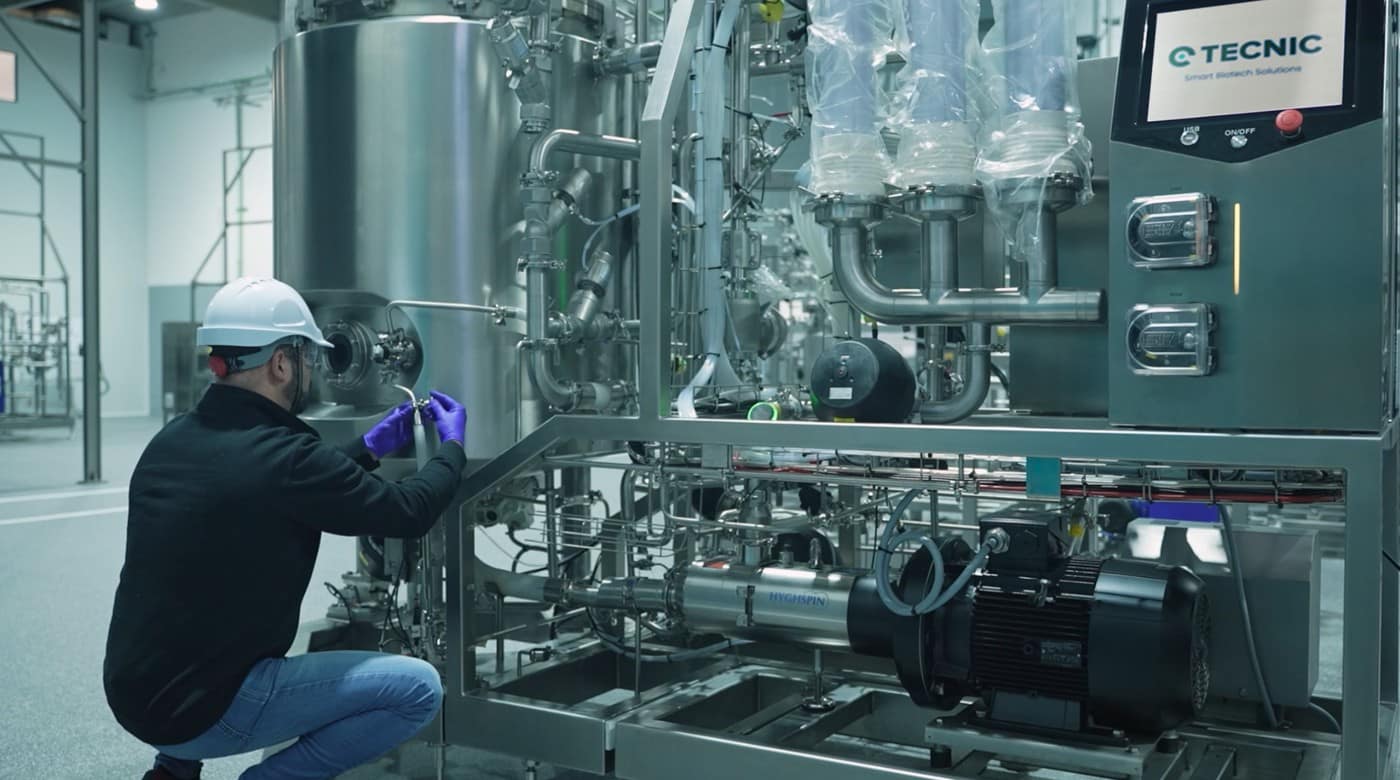
Continuous (constant-volume) diafiltration is the hydrodynamic engine of LNP purification. During this step, fresh formulation buffer is metered into the retentate vessel at the exact volumetric rate at which permeate liquid is removed through the membrane, maintaining retentate volume (Vret) perfectly constant.
Mathematical Mass Balance for Solvent Clearance
The removal rate of a freely permeating solvent species (like ethanol or citrate ions) during continuous diafiltration is governed by the differential mass balance:
d(Vret × C) / dt = − Qperm × Cperm
Because ethanol freely passes through the 100–500 kDa membrane pores without steric restriction, its sieving coefficient S = Cperm / Cret ≈ 1.0. With constant retentate volume (Vret = const):
dC / dt = − (Qperm / Vret) × C
Integrating from time t = 0 (initial concentration C0) to time t yields the classic exponential washout curve:
C(N) = C0 × exp(−N)
Where N = Vbuffer / Vret is the number of Diavolumes (DV) exchanged.
Step-by-Step Worked Engineering Sizing: 100 L Production Batch
Let us walk through a real-world sizing calculation for an MSAT scale-up engineer designing a commercial mRNA-LNP downstream train:
Engineering Design Inputs:
- Post-Mix Intermediate Volume: Vpost-mix = 100 L
- Initial Ethanol Concentration: 25% (v/v) = 250,000 ppm (parts per million)
- Target Residual Ethanol: ≤ 25 ppm (exceeding standard 50 ppm specifications)
- Volumetric Pre-Concentration Factor: 2.0× (reducing working volume to Vret = 50 L prior to diafiltration)
- Target Process Time for Diafiltration: ≤ 2.5 hours (150 minutes)
- Sustained Operational Flux (Hollow Fiber, 500 kDa mPES): J = 30 LMH (L/m2/h)
Step 1: Calculate Required Diavolumes (N)
Using the governing washout equation:
25 ppm = 250,000 ppm × exp(−N)
exp(N) = 250,000 / 25 = 10,000
N = ln(10,000) = 9.21 ≈ 9.5 Diavolumes
Step 2: Total Buffer Volume Required
Vbuffer = N × Vret = 9.5 × 50 L = 475 Liters of Formulation Buffer
Step 3: Sizing Membrane Surface Area (Amem)
The required volumetric permeate rate is:
Qperm = Vbuffer / ttarget = 475 L / 2.5 h = 190 L/h
At an operating flux of J = 30 LMH, the membrane area is:
Amem = Qperm / J = 190 L/h / 30 LMH = 6.33 m2
Engineering Implementation: The facility specifies a skid equipped with two 3.5 m2 (total 7.0 m2) 500 kDa mPES hollow fiber cartridges (0.5 mm lumen ID), running at a conservative flux of 27.1 LMH to provide a 10% safety margin against membrane fouling.
The Two-Stage Diafiltration Protocol
Industrial manufacturing recipes rarely perform all 9.5 diavolumes against a single buffer. Instead, best-in-class cGMP facilities execute a biphasic diafiltration protocol:
- Stage 1: Neutralization Diafiltration (4.0–5.0 DV): Buffer: 20 mM Tris, 100 mM NaCl, pH 7.4. This phase rapidly clears the bulk ethanol (>98% removal) while transitioning the pH across the ionizable lipid pKa threshold, solidifying the nanoparticle core while ionic strength remains isotonic.
- Stage 2: Formulation & Cryoprotectant Diafiltration (5.0–5.5 DV): Buffer: 10 mM Tris, 8.5% (w/v) Sucrose, pH 7.5. This phase clears the remaining residual ethanol to <25 ppm while washing out high NaCl salts and introducing sucrose, which stabilizes the lipid bilayer during subsequent ultra-cold storage (−80°C) and freeze-thaw cycles.
5. The 0.22 μm Sterile Filtration Roadblock: Why 80 nm Particles Blind 200 nm Pores
Of all unit operations in LNP manufacturing, none induces more anxiety among MSAT leads than terminal sterile filtration. In theory, passing an 80 nm spherical nanoparticle through a 220 nm (0.22 μm) sterilizing-grade filter pore should be trivial—the nominal pore diameter is nearly three times larger than the particle.
Yet in practice, mRNA-LNP sterile filtration regularly suffers catastrophic premature filter fouling. A filter rated to process 500 liters of protein drug product often blinds after processing barely 30 to 50 L/m2 of LNP retentate, causing transmembrane pressure to spike through the ceiling, halting processing, and endangering multi-million-dollar clinical batches.
The Four Biophysical Mechanisms of Sterile Filter Fouling
- Steric Bridging & Pore Constriction: Membrane pores are not clean cylindrical pipes; they are tortuous, interconnected polymeric sponge matrices with variable pore size distributions. When tens of millions of LNPs enter a pore throat simultaneously, hydrodynamic streamlines force particles to collide. Two or three 80 nm particles entering a 220 nm constriction bridge across the throat, creating an artificial sieving grid that rapidly catches incoming vesicles.
- Hydrophobic Surface Adsorption: Despite surface PEGylation, unshielded patches of hydrophobic cholesterol and ionizable lipids interact with hydrophobic domains on standard polyethersulfone (PES) or polyvinylidene fluoride (PVDF) polymer backbones. As LNPs adsorb onto pore walls, the effective lumen diameter narrows from 220 nm down to <100 nm, choking flow.
- Deformation & Vesicle Coalescence Under Pressure: Unlike rigid silica nanoparticles or icosahedral viral capsids (AAV, Lentivirus), LNPs are fluid, viscoelastic vesicles. When operators observe declining flow and respond by increasing differential pressure (ΔP > 1.0–1.5 bar), the elevated mechanical stress forces flexible LNPs into sub-micron pore tortuosities where they compress, burst, and coalesce into an impermeable, viscous lipid slime.
- Sub-Micron Aggregates in Retentate: During upstream TFF, any minor localized shear spikes produce trace amounts (<1%) of 200–400 nm fused vesicles. While invisible in standard intensity-weighted DLS measurements, these large aggregate outliers deposit preferentially onto the filter surface, accelerating cake filtration.
The Engineering Playbook to Prevent Sterile Filter Fouling
Industrial manufacturing teams eliminate sterile filtration fouling by standardizing on four critical engineering controls:
- Dual-Layer Asymmetric Membrane Architecture: Never attempt single-layer 0.22 μm filtration on LNPs. Use dual-layer integrated capsules featuring an asymmetric 0.8 μm or 0.45 μm prefilter layer permanently cast over a 0.20 μm sterilizing-grade layer (e.g., Millipore Express SHF, Sartorius Sartopore 2 XLG, or Pall Supor EKV). The open prefilter captures trace aggregates and pore-bridging precursors across its depth, protecting the final sterilizing layer from cake formation.
- Low-Binding Hydrophilic Surface Chemistry: Enforce the use of permanently hydrophilized polyethersulfone (PES) or hydrophilic PVDF with ultra-low lipid and protein binding properties. Standard un-modified PES membranes exhibit up to 10× higher lipid adsorption.
- Strict Differential Pressure Capping (ΔP ≤ 0.5 bar): Operate sterile filtration strictly under constant-flux pumping (10–25 LMH) or low regulated nitrogen top-pressure (≤ 0.5 bar / 7.5 psi). High pressures do not increase throughput; they trigger vesicle extrusion, deformation, and immediate pore plugging.
- Thermal Management Relative to Lipid Phase Transition (Tm): Standardize filtration temperature between 18°C and 22°C (ambient) rather than 2–8°C cold-room conditions. At cold temperatures, helper lipids (such as DSPC, with a gel-to-liquid transition temperature Tm ≈ 55°C) form rigid, highly resistant crystalline phases that increase suspension viscosity and pore resistance. Filtration at moderate ambient temperatures maintains favorable membrane fluidity and halves filtration resistance.
6. MSAT Troubleshooting Matrix: Diagnosing LNP Filtration Failures
When an LNP filtration run deviates in pilot development or cGMP manufacturing, process engineers use this diagnostic matrix to trace root causes and implement corrective actions:
| Observed Process Deviation | Probable Root Cause | Biochemical Mechanism | Immediate Corrective Action |
|---|---|---|---|
| Particle Size Jumps >20 nm During TFF (e.g., Z-avg climbs from 75 nm to 105 nm, PDI > 0.18). | Excessive wall shear stress or high pump pulsation. | Shear-induced stripping of PEG-lipids from vesicle surface allows bare hydrophobic cores to collide and fuse. | Reduce crossflow velocity to target γw ≤ 3,500 s-1. Replace peristaltic pump with low-pulsation 4-piston diaphragm pump (Quattroflow). |
| Encapsulation Efficiency Drops Below 80% | Premature neutralization buffer exchange before ethanol clearance. | Deprotonating ionizable amines while ethanol concentration remains >15% v/v destabilizes the inverted hexagonal RNA complex, causing cargo ejection. | Implement two-stage diafiltration: perform 3–4 DV of initial ethanol dilution prior to shifting pH above 7.0. |
| Severe Permeate Flux Decay Within 3 Diavolumes (>60% drop in LMH). | Operating above Critical Flux (J > Jcrit) under TMP control. | Concentration polarization overwhelms convective back-diffusion; soft LNPs form compressed, impermeable gel cake. | Switch from unrestricted open-permeate flow to permeate-metered pumping control. Throttle permeate pump to 65% of unconstrained flux. |
| Terminal 0.22 μm Sterile Filter Fouls at <50 L/m2 | Single-layer membrane selection or excessive differential pressure (ΔP > 1.2 bar). | Steric bridging across pore throats; high ΔP forces deformable vesicles to compress and coalesce in pore channels. | Switch to asymmetric dual-layer PES (0.8/0.2 μm). Regulate filtration pressure strictly ≤ 0.5 bar (7.5 psi) using nitrogen top-pressure. |
7. The Road Ahead: Continuous Countercurrent Membrane Purification
As genetic medicines transition from emergency pandemic response into high-volume chronic indications—such as PCSK9 cholesterol silencing, oncology neoantigen vaccines, and in vivo CAR-T cell reprogramming—batch TFF operations are confronting physical footprint and capital equipment constraints.
The next frontier in bioprocess engineering is the shift toward Continuous Countercurrent Tangential Flow Filtration (C-TFF) and single-pass tangential flow filtration (SPTFF). In these architectures, microfluidic formulation intermediates pass continuously through multi-stage staged hollow fiber modules without recirculation loops. By recycling buffer countercurrently against the advancing product stream, continuous TFF reduces formulation buffer consumption by 40–60%, eliminates product hold times, and enables fully integrated, closed end-to-end continuous mRNA-LNP drug substance manufacturing.
Accelerate Your Bioprocess & Membrane Sizing with BioFlo Workbench
Designing, scaling, and optimizing downstream biomanufacturing suites requires precise hydrodynamic modeling and verified mathematical rigor.
Explore BioFlo’s interactive calculation suites and modeling modules:
- Mixing Time & Hydrodynamic Shear Calculator: Model fluid shear dissipation, impeller tip speed, and Kolmogorov microscale boundaries across your vessels.
- Computational Fluid Dynamics (CFD) Multiphase Modeling: Simulate turbulent kinetic energy, boundary-layer mass transfer, and multi-scale flow regimes.
- C1V1 Solution & Buffer Preparation Planner: Precision multi-component dilution and diafiltration buffer recipe planner.
\ Get the latest news /